Subdivision hard surface modelling

Discussion for Level editing, modeling, programming, or any of the other technical aspects of Quake
Post Reply
obsidian
Posts: 10970
Joined: Mon Feb 04, 2002 8:00 am

Subdivision hard surface modelling

Post by obsidian »

Traditionally, I'm used to using 3ds Max for relatively low polygon mesh modelling but I'm starting to try my hand at working with much higher (million+) polygon models by using subdivision surface modelling. I'm not sure if many people model around here, but I'm asking for general tips.


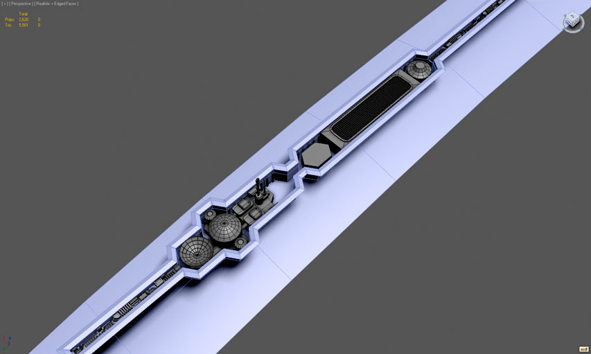
Starting off with a question, if I'm going to render things down to normalmaps, do I have to merge all the little detail meshes with the main mesh or can I just leave them floating on the surface with overlapping surfaces?

The main mesh is highlighted in blue, the detail stuff I want baked down to normalmaps is grey. This is part of a much larger spaceship model that I have saved on another file.

Image
[size=85][url=http://gtkradiant.com]GtkRadiant[/url] | [url=http://q3map2.robotrenegade.com]Q3Map2[/url] | [url=http://q3map2.robotrenegade.com/docs/shader_manual/]Shader Manual[/url][/size]
Silicone_Milk
Posts: 2237
Joined: Sat Mar 12, 2005 10:49 pm

Re: Subdivision hard surface modelling

Post by Silicone_Milk »

You can leave the gray mesh pieces floating above the blue surface and still bake a normalmap.
o'dium
Posts: 11712
Joined: Sun Mar 25, 2001 8:00 am

Re: Subdivision hard surface modelling

Post by o'dium »

Floating geo is perfectly fine, however its wise to note that if you float geo it will create breaks in smoothing groups obviously, so keep that in mind. Also, if you are going to float geo, remember that this could impact any AO maps you render. You will need to mess with different heights in this case, i.e.e move the floaters lower towards the mesh, but this can also impact z fighting and the like, depending on your set up.

As a rule, theres no rule :p Some things work sometimes, some things work other times.

However, the biggest tip I can give you is that a lot of what you have done above simply wont work. Theres a very simple reason for that, and its all to do with understanding how normal mapping works.

Think of a normal map as a colour. Purple. Well, purple/blue, but whatever. Now that is "flat", its perfectly flat with zero angle noise at all. Thats all well and good, but when you come to modelling actual detail, it isn't very good at all. The reason for this is that real life isn't much good with normal mapping. Take for example, the edge on most peoples computer desk. If we were to model that 100% realistic, we would set up the mesh as a box, i.e. like this:

|________________________|

But the problem there is that if you were to render that to texture, it would appear a simple flat single colour. Why? Because theres no "angles" in there for the normal rays to bounce off. So, right on those corners there, you would need to chamfer it slightly, so it would end up looking more like this:

\_____________________/

That produces angles for the rays to cast off, which in turn result in a much better look on the render to texture. As well as making sure you chamfer any hard edge, you also need to remember the scale of the chamfer plays heavily in what you are doing. Mipping, object scale and distance to camera origin all play a part in how big you should set chamfers up. For example:

Image

Of course, everything depends on what it actually is you are doing. For surface tetxures that you slap on walls, its a slightly different approach compared to say, a weapon model or anything of the sort. But DO try and keep the mesh as clean as possible so you can ouput different maps to help you. I can't really work without a resulting AO map, because it just sells it so much more. Plus using different blend mods in photoshop, you can use the resulting images CrazyBump pumps out for you so that all your edge work looks much more precise etc.
obsidian
Posts: 10970
Joined: Mon Feb 04, 2002 8:00 am

Re: Subdivision hard surface modelling

Post by obsidian »

o'dium wrote:Also, if you are going to float geo, remember that this could impact any AO maps you render. You will need to mess with different heights in this case.
How so, exactly. I do intend on rendering out AO later. What are the negative sides to floating geometry that will impact AO? Do you mean I may be able to sidestep some problems by embedding the floats deeper into the main mesh?
o'dium wrote:As well as making sure you chamfer any hard edge, you also need to remember the scale of the chamfer plays heavily in what you are doing.
I haven't done very much chamfering of edges yet, but I'm aware of that to some extent. It's also critical when I apply a Turbosmooth modifier for subdivisions, which I have not done. But as I understand it from your description, how much chamfering I need to apply depends on the eventual resolution output of the normal maps and I may need to exaggerate it? To give you an idea, the final model is going to be about 7km long, the spherical things on the model above are about 64m in diameter and the entire area on display above is about 1km. The camera will usually be about as close (or further) to the model as in the screenshot. I'll probably be using a bunch of high res textures to cover the whole thing.

Thanks, lots to think about. It's all quite daunting so I may have to scale down and try some more basic test models.
[size=85][url=http://gtkradiant.com]GtkRadiant[/url] | [url=http://q3map2.robotrenegade.com]Q3Map2[/url] | [url=http://q3map2.robotrenegade.com/docs/shader_manual/]Shader Manual[/url][/size]
o'dium
Posts: 11712
Joined: Sun Mar 25, 2001 8:00 am

Re: Subdivision hard surface modelling

Post by o'dium »

obsidian wrote:How so, exactly. I do intend on rendering out AO later. What are the negative sides to floating geometry that will impact AO? Do you mean I may be able to sidestep some problems by embedding the floats deeper into the main mesh?
Sounds complex, but its really simple to think about… The highest point on a mesh, is white. The lowest, is black. So obviously if something is higher than something else, it will be a different shade of greyscale. So, if you were to float geo, that would obviously be incorrect. It all depends on what exactly you want to do in that area, however. I’ve used floating geo before and as long as I’ve moved it close to the surface and made sure the mesh scale and cage were set up correctly, I haven’t had much if any issue at all, and the shade difference has been legible. But think of your AO map output as a “height map” of sorts, even if that’s wrong, it still works the same way, and floating geo will still change the outcome of the final texture.
obsidian wrote:I haven't done very much chamfering of edges yet, but I'm aware of that to some extent. It's also critical when I apply a Turbosmooth modifier for subdivisions, which I have not done. But as I understand it from your description, how much chamfering I need to apply depends on the eventual resolution output of the normal maps and I may need to exaggerate it? To give you an idea, the final model is going to be about 7km long, the spherical things on the model above are about 64m in diameter and the entire area on display above is about 1km. The camera will usually be about as close (or further) to the model as in the screenshot. I'll probably be using a bunch of high res textures to cover the whole thing.

Thanks, lots to think about. It's all quite daunting so I may have to scale down and try some more basic test models.
Its not so much the target resolution of the texture, more so the target scale of the asset. In this case that’s a pretty damn big model, and you would want (going from the size of that screenshot, the position the camera is at etc) at least a 2 pixel or so chamfer showing up there. But of course, when you went close up, that may look larger than it would in real life. But adding a subtle chamfer will work much, much better with the lighting and it will produce a much smoother falloff. Its best to just take a small piece, and test it. When you’re happy with that, go forth and do it the same on the rest.

Its quite a lot to take in, but its all common sense once you get down to the nitty gritty of it all.
Kat
Posts: 952
Joined: Tue Nov 14, 2000 8:00 am

Re: Subdivision hard surface modelling

Post by Kat »

AO's are about proximity, so whilst height and depth ends up being represented in tones of white/grey/black, for the bake process to work correctly you need to make sure your objects are positioned approximately near each other; you can get away with floating geo for normal maps because they're not specifically rendered in the same way (not necessarily based on proximity in the same way as AO and other maps are).

You also need to make sure that your floating geometry has a similar profile (where appropriate) to the object it's above otherwise the slight difference will cause discrepancies in the normal map and show up when rendered in game (or elsewhere). Watch out also for those right-angles you've got, they won't render well unless the low poly has them.

To answer your main question as to wither something will work... how big is that area going to be on your normal map. A couple of pixels? Half the map? An entire separate map? Be mindful of pixel density in other words.
[url=https://www.katsbits.com/tutorials#q3w]Tutorials, tools and resources[/url]
Post Reply